
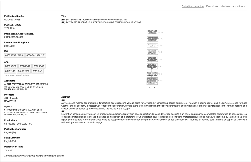
400-PO-WO/2020/157578
(EN) CONTAINER LASHING GEAR MONITORING SYSTEM
(FR) SYSTÈME DE SURVEILLANCE D'ENGRENAGE D'ARRIMAGE DE CONTENEUR
Sign-in for details of this Intellectual Property
PCT Biblio Data
| 62/798,331 | 29.01.2019 | US |
Description
Note: Text based on automatic Optical Character Recognition processes. Please use the PDF version for legal matters
CONTAINER LASHING GEAR MONITORING SYSTEM
FIELD OF THE INVENTION
[0001] This disclosure relates generally to monitoring systems for restraints, and more particularly, to a tension monitoring system for lashing gear applied to containers on container vessels.
BACKGROUND
[0002] A statement given by the World Shipping Council1 indicates that, during a survey period between 2014 and 2016, there were 612 containers lost at sea each year, excluding catastrophic loss. These losses happened despite routine checking of tension by the crews during the journies, and are most oftem are attributed to improper tensioning of lashing gear. Even in the cases where other causal factors are identified, the final component impacted before failure is the lashing gear. FIG. 1 shows a container vessel that has experienced container movement (and likely losses) as a result of improperly -tensioned lashing gear.
[0003] It is difficult to monitor container lashing tightness when the vessel is sailing. Containers can get loose for several reasons, including routine flexing of ship structure, bad weather, poor workmanship in loading and securing containers on borard. Normally, a container ship has several thousand containers stacked on top of each other multi-row configuration. This configuration makes container monitoring difficult. At present, the only effective way to monitor containers is by manually checking them at certain intervals during the sailing voyage period.
[0004] Manual systems for monitoring and maintaining lashing gear tension suffer several disadvantages. As the size of container ships increase over time, manual checking of tension during voyage becomes more costly, and is often not comprehensive and ineffective due to resource limitations. With increase in size of ships, it is not possible to visit each lashing rod with sufficient frequency to check its tightness. Even on a sampled basis, one estimate for example suggests manual checking require 2-3 hours time by two crew per day. Manual checking is also dangerous, with associated risks of crew falling overboard. One insurer estimates historical losses
1 See http://www.worldshipping.org/.
per lost container at between $100,000 to $1 million. Container losses may also generate an environmental impact with attendant costs (for example, from lost containers that are washed ashore).
[0005] Indirect methods of monitoring container security such as measuring the hull deformation and container deformation have been proposed in past. They do not directly measure the lashing rod tightness, and hence do not address the problem effectively.
[0006] It would be beneficial to develop a more effective and efficient system and method for monitoring and maintaining lashing gear tension.
SUMMARY
[0007] By way of example, aspects of the present disclosure are directed to disclose a novel system and method for remotely monitoring the lashing gear strain for containers being carried onboard ships (“SMARTLashing”) using fiber optic sensors and other associated hardware and software systems.
[0008] In accordance with aspects of the present disclosure, a system and method are disclosed for monitoring one or more objects that have been restrainedly secured to a vehicle by one or more restraint members. The system includes a plurality of sensors each configured for monitoring one or more of a compressive or tensile stress or strain in one of the one or more restraint members, and a controller for periodically interrogating each of the plurality of sensors to ascertain a value of stress or strain detected by the respective sensor. When a change in the value of stress or strain is indicative of loosened or overtightened restraint members, a mitigation event is triggered The stress or strain analysis distinguishes intermittent changes indicating a vehicle movement from sustained, gradual changes indicating a restraint member that has either been loosened or overtightened.
[0009] In accordance with an additional aspect of the disclosure, the vehicle is a container ship, the objects are containers, and the restraint members include lashing gear for securing the containers.
[00010] For a typical container ship carrying 1000 or more containers, in comparison to prior art methods requiring manual monitoring of container restraints, it is estimated that the system and method disclosed herein can reduce crew effort by 2-3 hrs. by 2 crew per day, prevent crew from falling overboard (Fig. l), and significantly reduce cost of associated insurance claims for injury and loss, which are estimated between $100k - $1 million per container loss. In addition, the impact on environment stemming from containers washed ashore can be substantially reduced.
[00011] This SUMMARY is provided to briefly identify some aspects of the present disclosure that are further described below in the DESCRIPTION. This SUMMARY is not intended to identify key or essential features of the present disclosure nor is it intended to limit the scope of any claims.
BRIEF DESCRIPTION OF THE DRAWING
[00012] A more complete understanding of the present disclosure may be realized by reference to the accompanying drawing in which:
[00013] FIG. 1 illustrates the impact improperly secured containers may exert on a container vessel;
[00014] FIGs. 2(a) - 2(d) illustrate container lashing rod configurations in accordance with aspects of the present disclosure;
[00015] FIGs. 3(a) - 3(c) further illustrate container lashing rod configurations in accordance with aspects of the present disclosure;
[00016] FIGs. 4(a) - 4(c) illustrate container layouts to which lashing rods are applied in accordance with aspects of the present disclosure;
[00017] FIGs. 5(a) and 5(b) illustrate strain sensor layouts in accordance with aspects of the present disclosure;
[00018] FIG. 6 provides a flow diagram illustrating a process for maintaining a tightness of lashing gear in accordance with aspects of the present disclosure;
[00019] FIGs. 7(a) - 7(c) illustrate exemplary sensor measures acquired for the purpose of measuring lashing rod strain in accordance with aspects of the present invention;
[00020] FIGs. 8(a) - 8(c) illustrate a positioning of strain sensors on lashing rods in accordance with aspects of the present disclosure;
[00021] FIGs. 9(a) and 9(b) illustrate exemplary sensor measures obtained from the sensors as positioned in FIGs. 8(a) - 8(c);
[00022] FIG. 10 further illustrates a positioning of a strain sensors on lashing rod in accordance with aspects of the present disclosure;
[00023] FIG. 11 provides an exemplary dashboard for monitoring lashing gear in accordance with aspects of the present disclosure;
[00024] FIGs. 12(a) and 12(b) present schematic diagrams illustrating an exemplary cable layout for a lashing gear monitoring system in accordance with aspects of the present disclosure; and
[00025] FIG. 13 further illustrates the exemplary layout of FIGs. 12(a) and 12(b).
DETAILED DESCRIPTION
[00026] The following merely illustrates the principles of the disclosure. It will thus be appreciated that those skilled in the art will be able to devise various arrangements which, although not explicitly described or shown herein, embody the principles of the disclosure and are included within its spirit and scope.
[00027] Furthermore, all examples and conditional language recited herein are principally intended expressly to be only for pedagogical purposes to aid the reader in understanding the principles of the disclosure and the concepts contributed by the inventor(s) to furthering the art, and are to be construed as being without limitation to such specifically recited examples and conditions.
[00028] Moreover, all statements herein reciting principles, aspects, and embodiments of the disclosure, as well as specific examples thereof, are intended to encompass both structural and functional equivalents thereof. Additionally, it is intended that such equivalents include both currently known equivalents as well as equivalents developed in the future, i.e., any elements later developed that perform the same function, regardless of structure.
[00029] Unless otherwise explicitly specified herein, the drawings are not drawn to scale.
[00030] Aspects of the present disclosure are directed to an inventive system and method for monitoring and maintaining lashing gear tension of a container vessel. Elements of the inventive system include lashing rods, optical strain sensors (preferably,“fiber Bragg grating” or “FBG” sensors), an interrogator unit for polling the optical strain sensors to obtain strain data, optical fiber cables for optical communications between the interrogator unit and strain sensors, and a general-purpose computer and monitor for operating the system.
[00031] Some other non-optical strain monitoring solutions require extensive power cable networks on board ship, and are difficult to implement. Also, the environment on deck is often harsh, and components are required to be environmentally robust and explosion-proof. This makes many other possible strain monitoring solutions impractical to implement on board merchant vessels.
[00032] FIGs. 2(a) - 4(c) illustrate container lashing arrangements in accordance with aspects of the present disclosure. As shown for example in FIG. 3, containers 13 are arranged in column stacks 16 in which vertically adjacent ones of the containers 13 are fixedly fastened to one another. Column stacks 16 are subjected to a variety of forces (for example, resulting from wind and motion of the vessel 10 asea that can be characterized as one or more of pitch motion, heave motion and roll motion) which further require that the column stacks 16 be secured to the deck 18 of the vessel 10. This is typically accomplished by mechanically fastening one or more containers in the column stack to the deck 18 by means of lashing rods 20 that are preferably fastened at one end to a receptacle affixed to a container 13 and at the other end to a lashing bridge 11 that is integral with and/or afficxed to the deck 18 (see, e.g., FIGs. 2(a) and 2(b)). With reference to FIG.
10, lashing rods 20 may preferably include a tumbuckle 22 with a threaded rod connected to a shackle 21 on one end, and a rod extending from the other end that terminates in a second shackle 21. The turnbuckle 22 provides a mechanism for loosening or tightening the lashing rods 20 in order to properly secure the associated containers 13 to the deck 18. In accordance with aspects of the present disclosure, and as depicted in FIG. 3(c), suitable lashing gear may included a model ST-4508 knob/jaw tumbuckle and LB-44 lashing bar, both available from International Lashing Systems NV of Antwerp, Belgium.
[00033] Lashing rods 20 are preferably applied in a selective manner to a limited number of containers 13 to secure the containers 13 to the deck 18. FIGs. 2(c) and 2(d) illustrate two non limiting examples of such selective applications. In FIG. 2(d), two crossing lashing rods 13 are attached to opposing lashing bridges 11 in proximity to a lower containers 13. The tumbuckles 22 are each coupled to a twin rod and shackle arrangement that is respectively coupled to one receptacle that is integral with an upper corner of the lower container 13 and to another shackle arrangement that is coupled to a second receptacle that is integral with a lower corner of a vertically adjacent container 13 (see, eg., FIG. 2a). An equalizing device (for example, toggle plate 21a) is preferably positioned between the turnbuckles 22 and twin rod and shackle arrangement to equalize the forces applied by each lashing rod 20 to the corners of the two containers. In the example of FIG. 2(c), a pair lashing rods 20 are attached to each of the opposing lashing bridges
11, with one of the lashing rod pair being coupled to a receptacle that is integral with an upper corner of the lower container 13 and the other one of the lashing rod pair being coupled to a another receptacle that is integral with an upper corner of a vertically adjacent container 13.
[00034] FIGs. 4(a) - 4(c) illustrate a lashing rod monitoring scheme in accordance with aspects of the present invention. A typical container vessel 10 may carry several thousand containers. A suitable monitoring scheme should ideally be capable of ensuring that lashing tightness of all containers is comprehensively covered without having the need to fit all lashing rods with sensors. For this purpose, the inventors determined by experimentation and by studying causal factors for container lashing becoming loose or tight that sensors could be applied to lashing rods associated with just two rings of the most vulnerable container stacks. As illustrated for example in FIGs. 4(a) - 4(c), these rings include containers 13 occupying one or two tiers 12 of the outermost stack rows 14a on the deck 18 of the container vessel 10, and at least one tier of the outermost stack rows 15b having a highest stack weight. Other containers deemed to be especially vulnerable may optionally be added for monitroring as well.
[00035] The inventors further determined that the number of sensors 24 used in each ring cant be selectively reduced without significantly impacting the ability of the system to detect tensioning anomalies for the lashing rods 20. Specifically, for example, as illustrated by FIG. 5(a), sensors 24 can alternatively be omitted on each of port and starboard sides from adjacent bays 14, such that each bay 14 has sensors 24 positioned on only one of the sides (port or starboard) of the bay. As another example illustrated by FIG. 5(b), the sumber of sensors on port and starboard sides in each bay can be reduced (for example, eliminating sensors on either the for or aft lashing rods 20 on each side).
[00036] FIGs. 8(a) - 8(c) and FIG. 10, in accordance with aspects of the present disclosure, illustrates sensor configurations as applied to the lashing rods 20. As depicted, strain gauges are applied along a longitidinal axis of the lashing rods 20. The sensors 25, 26 depicted in FIGs. 8(a) - 8(c) and FIG. 10 are optical strain gauges (a suitable gauge for this purpose is the OS3100 optical strain gauge available from Micron Optics, Inc. of Atlanta, Georgia). The OS3100 optical strain gauge incorporates a fiber Bragg grating (FBG) configured as a fiber Fabry -Perot interferometer . FIG. 8(a) illustrates a first configuration, in which a long strain-sensing gauge 25 is affixed to the tumbuckle 22 of the lashing rod 20. FIG. 8 (c) and FIG. 10 illustrate a second configuration, in which a short strain-sensing gauge is affixed to the shackle 21 of the lashing rod 20. Strain is measured by sending a laser beam through the FBG sensor fitted on the lashing gear, and measuring the change in wavelength. For ease of identification, ach sensor is assigned a unique wavelength. This approach minimizes the amout of required cabling, and supports a modular, scalable infrastructure which is practical and easy to implement.
[00037] Long strain gauge sensors 25 are fitted along the length of the turnbuckle 22 of the lashing gear 20. These gauges are fitted across the entire length of the turnbuckle 22 in longitudinal direction. The inventors determined however that this configuration is difficult to maintain since the turnbuckle needs to be rotated. Short strain gauge sensors 26 on the other hand are fitted on the lower shackle, after machining the surface. The inventors found that, while measurements are magnified for the long strain gauge sensors 25 as compared to the short strain gauge sensors 26, deviations were accurately captured in both cases. FIGs. 9(a) and 9(b) illustrate outputs for the long strain gauge sensors 25 and the short strain gauge sensors 26, respectively. As a result, a preferred implementation uses the short strain gauge sensors 26.
[00038] Since the FBG sensors are very sensitive to variation in temperature, an additional sensor is used in each case for measuring temperature. Compensation for temperature is made to accurately measure strain due to movement of ship and other factors. FIGs. 7(a) - 7(c) illustrate the measurement process. In FIG. 7(a), a measure of change in wavelength over time is obtained by the strain gauge. FIG. 7(b) illustrates the output of the isolates sensor, which indicates a change in wavelength over time due only to temperature effects. In order to produce the output of FIG. 7(b), a second FBG sensor may be provided in proximity to the strain gauge but isolated from exposure to forces inducing strain. Alternatively, as optical fiber rates of expansion and contraction due to temperature are readily known, the change in wavelength due to temperature can simply be calculated to represent the output of FIG. 7(b). As illustrated in FIG. 7(c), a difference between the wavelength values illustrated in FIGs. 7(a) and 7(b) can then be calculated to determine temperature-compensated strain levels.
[00039] In accordance with aspects of the present disclosure, FIGs. 12(a), 12(b) and 13 illustrate an overall architecture for the container lashing gear monitoring system. Each of the strain gauge sensors 24 and temperatures sensors are coupled via sensor cables 27 and sensor
connectors 28 to backbone connectors 38 of an optical fiber backbone 37. Each backbone connector 38 connects sensors from several lashing rods 20 to the optical fiber backbone, which runs across the length of the ship in order to provide access to all containers onboard the ship.
[00040] An interrogator unit 32, which is preferably housed within the ship, determines lashing rod strain from measurements provided by the sensors 24. The interrogator unit 32 is preferably implemented by a Hyperion s255 Hyperion Optical Sensing Instrument, available from Micron Optics, Inc. of Atlanta, Georgia. Individual sensors incorporate a light source having a unique wavelength, and thus are able to continuously and identifiably monitor changes in lashing rod tightness for monitored lashing rods 20. Each backbone connector 38 may for example connect up to 16 sensors to optical splines that are integrated with the backbone 37.
[00041] Some of the sensors 24 are fixedly attached to the connectors 38, and some are additionally connected to the connectors 38 via one or more free ports 33. Interrogator unit 32 is further coupled (for example, via LAN cable 35) to a general purpose computer 34 nd associated display 36 that funtion to provide a continuous monitoring display and alarm unit for the container lashing gear monitoring system.
[00042] Continuous monitoring display and alarm unit 34, 36 may preferably display a dashboard that is used by operators to identify alert conditions. On this screen, an operator can see a current status of each lashing rod 20 (normal or alarm state), together with strain and historical data. For example, with reference to FIG.11, the user is able to select a particular sensor 24 (ID No. 1512082126) that is assigned to a lashing rod 20 positioned at bay 3, row 7, tier 1. Graphic 40 depicts the location of the associated container 13 on deck 18 of the vessel 10. Graphic 42 indicates that a“tension warning” was initially issued indicating a tension level that exceeds a baseline value (0.58 nm”), and a“tension alert” was later issued when the exceeded baseline value remained for a predetermined number of measurement and/or time period. One of skill in the art will readily envision many other modes of display are possible for the monitoring and alarm functions. It is possbile that Interrogator unit 32 may be coupled to existing on-board monitoring and alert systems for the purpose of implementing the continuous monitoring display and alarm unit 34, 36.
[00043] FIG. 6 illustrates an exemplary method for operating the container lashing gear monitoring system according to aspects of the present disclosure suitable software. At step 602 of the method, sensors 24 are identified and fitted to lashing rods 20 according to a selected desgin (for example, as depicted in FIG. 4(b). At step 604, thelashing gear 20 is tightened according to accepted specifications.2 At step 606, sensor data is collected at a regular interval (for example, with a frequency of 1 Hz), and algorithms are applied to filter increases in strain force that are due only to ship movement. At step 608, additional algorithma are applied to look for sustrained and gradual strains that are indicative of a loosening of associated lashing rods 20. At step 610, an alert decision is made when the change and duration of strain exceed a threshold indicating a loosening of associated lashing rods 20. At step 612, upon receipt of the alert, ship crew are dispatched to mitigate the loosening condition by re-tightening the associated lashing gear 20 to prescribed specifications.
[00044]It will be understood that, while various aspects of the present disclosure have been illustrated and described by way of example, the invention claimed herein is not limited thereto, but may be otherwise variously embodied within the scope of the following claims. For example, the system may be readily adapted for application to other mechanical systems both onboard the vessel 10 (including engine rooms) and/oror other operating environments - for example, including tie rods, foundation bolts and other long bolting arrangements subject to cyclic stress and strain.
[00045] The following table lists the reference characters and names of features and elements used herein: Reference characters assigned to method steps are not listed.
2 See, e.g.“Stowage and Lashing of Containers,” Rules for Classification and Construction: Ship Technology, Germanischer Lloyd, Hamburg, Germany, 2013 and“A Master’s Guide to Container Securing,” 2nd Edition, Lloyd’s Register, 2012.